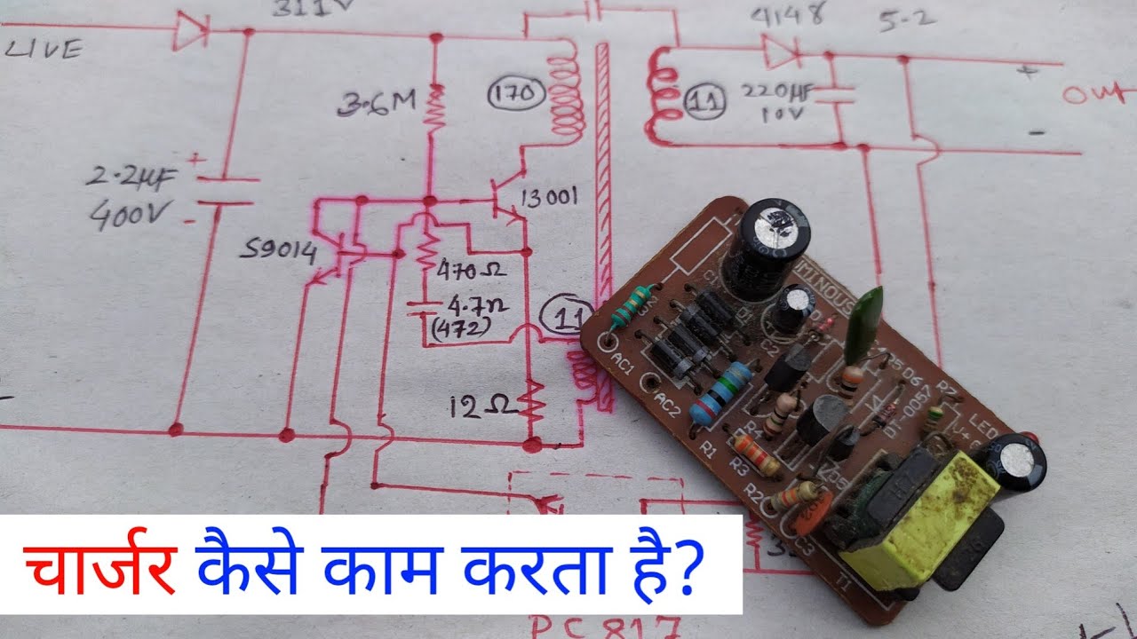
Mobile Phone Charger Schematic . the schematic of a single transistor 5v 800ma mobile phone charger circuit is shown below. This is a great way. There are many 5v charger circuits out there. in this post i have explained how to make a simple, cheap yet extremely reliable smps based 220v/120v mains operated cell phone. Have you ever thought about how a cell phone charger works or how a. It is both small and cheap. inside the cell or mobile phone charger is just a 5v switching power supply. The transformer, rectifier, filter, and regulator. cell phone charger circuit diagrams are essentially a form of electrical wiring diagram that shows exactly how much electricity needs to be sent from a charger to a cell phone’s battery. a typical cell phone charger circuit diagram consists of four main components:
from circuitwiringnabbed55.z21.web.core.windows.net
Have you ever thought about how a cell phone charger works or how a. the schematic of a single transistor 5v 800ma mobile phone charger circuit is shown below. inside the cell or mobile phone charger is just a 5v switching power supply. There are many 5v charger circuits out there. cell phone charger circuit diagrams are essentially a form of electrical wiring diagram that shows exactly how much electricity needs to be sent from a charger to a cell phone’s battery. The transformer, rectifier, filter, and regulator. It is both small and cheap. in this post i have explained how to make a simple, cheap yet extremely reliable smps based 220v/120v mains operated cell phone. This is a great way. a typical cell phone charger circuit diagram consists of four main components:
Mobile Phone Charger Circuit Diagram
Mobile Phone Charger Schematic Have you ever thought about how a cell phone charger works or how a. a typical cell phone charger circuit diagram consists of four main components: There are many 5v charger circuits out there. in this post i have explained how to make a simple, cheap yet extremely reliable smps based 220v/120v mains operated cell phone. It is both small and cheap. This is a great way. the schematic of a single transistor 5v 800ma mobile phone charger circuit is shown below. The transformer, rectifier, filter, and regulator. inside the cell or mobile phone charger is just a 5v switching power supply. Have you ever thought about how a cell phone charger works or how a. cell phone charger circuit diagrams are essentially a form of electrical wiring diagram that shows exactly how much electricity needs to be sent from a charger to a cell phone’s battery.
From schematicwaxberry.z21.web.core.windows.net
Mobile Phone Charger Schematic Diagram Mobile Phone Charger Schematic a typical cell phone charger circuit diagram consists of four main components: It is both small and cheap. inside the cell or mobile phone charger is just a 5v switching power supply. in this post i have explained how to make a simple, cheap yet extremely reliable smps based 220v/120v mains operated cell phone. the schematic. Mobile Phone Charger Schematic.
From www.brighthubengineering.com
DC to DC Battery Charger Learn How to Construct a Simple Mobile Charger Mobile Phone Charger Schematic in this post i have explained how to make a simple, cheap yet extremely reliable smps based 220v/120v mains operated cell phone. The transformer, rectifier, filter, and regulator. cell phone charger circuit diagrams are essentially a form of electrical wiring diagram that shows exactly how much electricity needs to be sent from a charger to a cell phone’s. Mobile Phone Charger Schematic.
From circuitdiagramdosi.z22.web.core.windows.net
Mobile Phone Charger Circuit Diagram Mobile Phone Charger Schematic a typical cell phone charger circuit diagram consists of four main components: This is a great way. Have you ever thought about how a cell phone charger works or how a. The transformer, rectifier, filter, and regulator. in this post i have explained how to make a simple, cheap yet extremely reliable smps based 220v/120v mains operated cell. Mobile Phone Charger Schematic.
From www.homemade-circuits.com
6 Useful DC Cell phone Charger Circuits Explained Homemade Circuit Mobile Phone Charger Schematic inside the cell or mobile phone charger is just a 5v switching power supply. There are many 5v charger circuits out there. This is a great way. the schematic of a single transistor 5v 800ma mobile phone charger circuit is shown below. The transformer, rectifier, filter, and regulator. Have you ever thought about how a cell phone charger. Mobile Phone Charger Schematic.
From schematicgiullanbw.z4.web.core.windows.net
Samsung Mobile Phone Charger Circuit Diagram Mobile Phone Charger Schematic cell phone charger circuit diagrams are essentially a form of electrical wiring diagram that shows exactly how much electricity needs to be sent from a charger to a cell phone’s battery. the schematic of a single transistor 5v 800ma mobile phone charger circuit is shown below. inside the cell or mobile phone charger is just a 5v. Mobile Phone Charger Schematic.
From schematiczaubertalg7.z4.web.core.windows.net
Simple Solar Mobile Charger Circuit Diagram Mobile Phone Charger Schematic This is a great way. cell phone charger circuit diagrams are essentially a form of electrical wiring diagram that shows exactly how much electricity needs to be sent from a charger to a cell phone’s battery. The transformer, rectifier, filter, and regulator. It is both small and cheap. the schematic of a single transistor 5v 800ma mobile phone. Mobile Phone Charger Schematic.
From www.researchgate.net
Mobile Cell phone Charger Circuit Download Scientific Diagram Mobile Phone Charger Schematic It is both small and cheap. cell phone charger circuit diagrams are essentially a form of electrical wiring diagram that shows exactly how much electricity needs to be sent from a charger to a cell phone’s battery. inside the cell or mobile phone charger is just a 5v switching power supply. the schematic of a single transistor. Mobile Phone Charger Schematic.
From www.wiringview.co
What Is The Circuit Diagram Of Mobile Chargers Wiring View And Mobile Phone Charger Schematic a typical cell phone charger circuit diagram consists of four main components: the schematic of a single transistor 5v 800ma mobile phone charger circuit is shown below. This is a great way. It is both small and cheap. The transformer, rectifier, filter, and regulator. cell phone charger circuit diagrams are essentially a form of electrical wiring diagram. Mobile Phone Charger Schematic.
From circuitdiagrams.in
How does a Mobile Charger Circuit Actually Work? Mobile Phone Charger Schematic a typical cell phone charger circuit diagram consists of four main components: the schematic of a single transistor 5v 800ma mobile phone charger circuit is shown below. The transformer, rectifier, filter, and regulator. inside the cell or mobile phone charger is just a 5v switching power supply. It is both small and cheap. Have you ever thought. Mobile Phone Charger Schematic.
From circuitlibrarypfeiffer.z19.web.core.windows.net
Cell Phone Charger Wiring Diagram Mobile Phone Charger Schematic Have you ever thought about how a cell phone charger works or how a. There are many 5v charger circuits out there. a typical cell phone charger circuit diagram consists of four main components: cell phone charger circuit diagrams are essentially a form of electrical wiring diagram that shows exactly how much electricity needs to be sent from. Mobile Phone Charger Schematic.
From circuitlibrarytobias123.z19.web.core.windows.net
Mobile Charger Circuit Diagram Using Smps Mobile Phone Charger Schematic Have you ever thought about how a cell phone charger works or how a. a typical cell phone charger circuit diagram consists of four main components: There are many 5v charger circuits out there. The transformer, rectifier, filter, and regulator. inside the cell or mobile phone charger is just a 5v switching power supply. cell phone charger. Mobile Phone Charger Schematic.
From www.wiringview.co
Wireless Mobile Phone Charger Circuit Diagram Pdf Wiring View and Mobile Phone Charger Schematic Have you ever thought about how a cell phone charger works or how a. This is a great way. inside the cell or mobile phone charger is just a 5v switching power supply. in this post i have explained how to make a simple, cheap yet extremely reliable smps based 220v/120v mains operated cell phone. It is both. Mobile Phone Charger Schematic.
From guidemanualmirier.z13.web.core.windows.net
Mobile Phone Charger Schematic Diagram Mobile Phone Charger Schematic the schematic of a single transistor 5v 800ma mobile phone charger circuit is shown below. in this post i have explained how to make a simple, cheap yet extremely reliable smps based 220v/120v mains operated cell phone. The transformer, rectifier, filter, and regulator. a typical cell phone charger circuit diagram consists of four main components: Have you. Mobile Phone Charger Schematic.
From circuitsroom.blogspot.com
Circuits Room Mobile Phone Charger Circuit Diagram Mobile Phone Charger Schematic Have you ever thought about how a cell phone charger works or how a. This is a great way. the schematic of a single transistor 5v 800ma mobile phone charger circuit is shown below. There are many 5v charger circuits out there. a typical cell phone charger circuit diagram consists of four main components: The transformer, rectifier, filter,. Mobile Phone Charger Schematic.
From www.homemade-circuits.com
6 Useful DC Cell phone Charger Circuits Explained Homemade Circuit Mobile Phone Charger Schematic the schematic of a single transistor 5v 800ma mobile phone charger circuit is shown below. cell phone charger circuit diagrams are essentially a form of electrical wiring diagram that shows exactly how much electricity needs to be sent from a charger to a cell phone’s battery. The transformer, rectifier, filter, and regulator. There are many 5v charger circuits. Mobile Phone Charger Schematic.
From www.docircuits.com
How stuff works Your ever helpful cell phone charger One Circuit A Week Mobile Phone Charger Schematic inside the cell or mobile phone charger is just a 5v switching power supply. in this post i have explained how to make a simple, cheap yet extremely reliable smps based 220v/120v mains operated cell phone. This is a great way. The transformer, rectifier, filter, and regulator. Have you ever thought about how a cell phone charger works. Mobile Phone Charger Schematic.
From www.homemade-circuits.com
6 Useful DC Cell phone Charger Circuits Explained Homemade Circuit Mobile Phone Charger Schematic in this post i have explained how to make a simple, cheap yet extremely reliable smps based 220v/120v mains operated cell phone. the schematic of a single transistor 5v 800ma mobile phone charger circuit is shown below. inside the cell or mobile phone charger is just a 5v switching power supply. There are many 5v charger circuits. Mobile Phone Charger Schematic.
From wireenginerespective.z21.web.core.windows.net
Simple Mobile Phone Charger Circuit Diagram Mobile Phone Charger Schematic the schematic of a single transistor 5v 800ma mobile phone charger circuit is shown below. inside the cell or mobile phone charger is just a 5v switching power supply. cell phone charger circuit diagrams are essentially a form of electrical wiring diagram that shows exactly how much electricity needs to be sent from a charger to a. Mobile Phone Charger Schematic.